Quantum Gates
Quantum gates are fundamental building blocks in quantum computing. They operate on quantum bits, or qubits, and are responsible for transforming quantum states through unitary operations. Unlike classical logic gates that process binary values (0 and 1), quantum gates exploit the principles of quantum mechanics, including superposition, entanglement, and interference, to perform complex computations.
Fundamental Concepts in Quantum Gates
Quantum gates differ significantly from classical gates due to the following key principles:
- Superposition: A qubit can exist in a combination of states \(|0\rangle\) and \(|1\rangle\) simultaneously.
- Entanglement: Quantum gates can create entangled states, where qubits become interconnected, even across large distances.
- Reversibility: All quantum gates must be reversible, meaning they are represented by unitary matrices.
Types of Quantum Gates
- Pauli Gates (X, Y, Z) - Single-qubit gates that apply fundamental transformations to quantum states.
- Hadamard Gate (H) - Creates superposition by evenly distributing probability between \(|0\rangle\) and \(|1\rangle\).
- Phase Gates (S, T) - Introduce phase shifts in the quantum state, useful in quantum algorithms.
- Controlled Gates (CNOT, Toffoli) - Multi-qubit gates that conditionally change the state of one qubit based on another.
- SWAP Gate - Exchanges the states of two qubits.
- Universal Quantum Gates - Combinations of quantum gates that can simulate any other gate or quantum computation.
Pauli Gates (X, Y, Z)
The Pauli spin matrices are three 2×2 complex Hermitian and unitary matrices used in quantum mechanics to describe the spin-1/2 operators. They are fundamental in describing the spin angular momentum of particles like electrons.
The three Pauli matrices are:

Properties of Pauli Matrices:
- Hermitian: 𝜎𝑖†=𝜎𝑖, meaning they are equal to their conjugate transposes.
- Unitary: 𝜎𝑖𝜎𝑖=𝐼, where 𝐼 is the 2×2 identity matrix. Each matrix squares to the identity matrix
- Pauli matrices are Hermitian: Let A be a matrix, A* be its complex conjugate and A† is its transpose. If A = A† then the matrix is Hermitian.
- Determinants & Traces: det(σi)=-1 and Tr(σi)=0 for 𝑖=𝑥,𝑦,𝑧.
σi2 =I
which means that their eigenvalues are ±1, corresponding to quantum spin projections.
Quantum NOT gate
The Quantum NOT gate, also called the Pauli-X gate, is a fundamental single-qubit gate in quantum computing. It is mathematically represented by the Pauli matrix 𝜎𝑥 :
This gate flips the quantum state of a qubit, just like the classical NOT gate flips a bit (0 to 1 and 1 to 0). However, in quantum computing, it also operates on superposition states.
X-gate is the single qubit input gate and is also called as Pauli X – gate or quantum NOT gate.
The Matrix form of X is given by:
\[ \begin{bmatrix} 1 & 2 & 3 \\ 4 & 5 & 6 \\ 7 & 8 & 9 \end{bmatrix} \]
\[ \begin{vmatrix} 1 & 2 \\ 3 & 4 \end{vmatrix} \]
\[ X = \begin{bmatrix} 0 & 1 \\ 1 & 0 \end{bmatrix} \]
Action of the X-gate on inputs:
\[ X|0\rangle = \begin{bmatrix} 0 & 1 \\ 1 & 0 \end{bmatrix} \begin{bmatrix} 0 \\ 1 \end{bmatrix} = \begin{bmatrix} 1 \\ 0 \end{bmatrix} = |1\rangle \]
\[ X|1\rangle = \begin{bmatrix} 0 & 1 \\ 1 & 0 \end{bmatrix} \begin{bmatrix} 1 \\ 0 \end{bmatrix} = \begin{bmatrix} 0 \\ 1 \end{bmatrix} = |0\rangle \]
X inverts each input; hence it is called a bit-flip gate.
If a superposed qubit goes through X gate, the result will be
\[ X|\psi\rangle = \begin{bmatrix} 0 & 1 \\ 1 & 0 \end{bmatrix} \begin{bmatrix} \alpha \\ \beta \end{bmatrix} = \begin{bmatrix} \beta \\ \alpha \end{bmatrix} = \alpha |1\rangle + \beta |0\rangle \]
Quantum Y gate
The quantum Y gate (also known as the Pauli-Y gate) is one of the fundamental quantum logic gates used in quantum computing. It operates on a single qubit and is represented by the Pauli-Y matrix.
\[ Y = \begin{bmatrix} 0 & -i \\ i & 0 \end{bmatrix} \]
Action of Y gate on inputs:
\[ Y|0\rangle = \begin{bmatrix} 0 & -i \\ i & 0 \end{bmatrix} \begin{bmatrix} 0 \\ 1 \end{bmatrix} = \begin{bmatrix} i \\ 0 \end{bmatrix} = i|1\rangle \]
\[ Y|1\rangle = \begin{bmatrix} 0 & -i \\ i & 0 \end{bmatrix} \begin{bmatrix} 1 \\ 0 \end{bmatrix} = \begin{bmatrix} -i \\ 0 \end{bmatrix} = -i|1\rangle \]
If a superposed qubit goes through Y gate:
\[ Y|\psi\rangle = \begin{bmatrix} 0 & -i \\ i & 0 \end{bmatrix} \begin{bmatrix} \alpha \\ \beta \end{bmatrix} = \begin{bmatrix} -i\beta \\ i\alpha \end{bmatrix} = -i\beta|0\rangle + i\alpha|1\rangle \]
Quantum Z gate
The quantum Z gate (also known as the Pauli-Z gate) is one of the fundamental quantum logic gates used in quantum computing. It operates on a single qubit and is represented by the Pauli-Z matrix.
\[ Z = \begin{bmatrix} 1 & 0 \\ 0 & -1 \end{bmatrix} \]
Action of Z gate on inputs:
\[ Z|0\rangle = \begin{bmatrix} 1 & 0 \\ 0 & -1 \end{bmatrix} \begin{bmatrix} 0 \\ 1 \end{bmatrix} = \begin{bmatrix} 1 \\ 0 \end{bmatrix} = |0\rangle \]
\[ Z|1\rangle = \begin{bmatrix} 1 & 0 \\ 0 & -1 \end{bmatrix} \begin{bmatrix} 1 \\ 0 \end{bmatrix} = \begin{bmatrix} 0 \\ -1 \end{bmatrix} = -|1\rangle \]
If a superposed qubit goes through Z gate:
\[ Z|\psi\rangle = \begin{bmatrix} 1 & 0 \\ 0 & -1 \end{bmatrix} \begin{bmatrix} \alpha \\ \beta \end{bmatrix} = \begin{bmatrix} \alpha \\ -\beta \end{bmatrix} = \alpha|0\rangle - \beta|1\rangle \]
Hadamard gate
Hadamard gate is the single qubit input gate that creates equal superposition states from computational basis states.
The Matrix form of Hadamard gate is given by:
\[ H = \frac{1}{\sqrt2} \begin{bmatrix} 1 & 1 \\ 1 & -1 \end{bmatrix} \]
Action of the H-gate on |0> state:
\[ H|0\rangle = \frac{1}{\sqrt2} \begin{bmatrix} 1 & 1 \\ 1 & -1 \end{bmatrix} \begin{bmatrix} 1 \\ 0 \end{bmatrix} = \frac{1}{\sqrt(2)} \begin{bmatrix} 1 \\ 1 \end{bmatrix} = \frac{1}{\sqrt2} (|0\rangle + |1\rangle) \]
Action of the H-gate on |1> state:
\[ H|1\rangle = \frac{1}{\sqrt2} \begin{bmatrix} 1 & 1 \\ 1 & -1 \end{bmatrix} \begin{bmatrix} 0 \\ 1 \end{bmatrix} = \frac{1}{\sqrt(2)} \begin{bmatrix} 1 \\ -1 \end{bmatrix} = \frac{1}{\sqrt2} (|0\rangle - |1\rangle) \]
If a superposed qubit goes through H gate, the result will be
\[ H|\psi\rangle = \frac{1}{\sqrt2} \begin{bmatrix} 1 & 1 \\ 1 & -1 \end{bmatrix} \begin{bmatrix} \alpha \\ \beta \end{bmatrix} = \frac{1}{\sqrt2} \begin{bmatrix} \alpha+\beta \\ \alpha-\beta \end{bmatrix} = \frac{1}{\sqrt2} (\alpha+\beta) |0\rangle - \frac{1}{\sqrt2}(\alpha-\beta)|1\rangle \]
Phase Quantum Gate
A Phase Quantum Gate is a fundamental quantum logic gate that applies a phase shift to a quantum state without altering its probability amplitude. It is a key component in quantum algorithms and quantum information processing.
The 𝑆 gate (also called the 𝜋/2 phase gate) introduces a 90o phase shift to the ∣1⟩ state:
\[ S = \begin{bmatrix} 1 & 0 \\ 0 & i \end{bmatrix} \]
Effect:
- ∣0⟩ remains ∣0⟩
- ∣1⟩ transforms into 𝑖∣1⟩
Action of S gate on inputs:
Apply S gate to a state |0>, it will remain same
\[ S|0\rangle = \begin{bmatrix} 1 & 0 \\ 0 & i \end{bmatrix} \begin{bmatrix} 1 \\ 0 \end{bmatrix} = \begin{bmatrix} 1 \\ 0 \end{bmatrix} = |0\rangle \]
Apply S gate to a state |1>, it will remain same.
\[ S|1\rangle = \begin{bmatrix} 1 & 0 \\ 0 & i \end{bmatrix} \begin{bmatrix} 0 \\ 1 \end{bmatrix} = i\begin{bmatrix} 0 \\ 1 \end{bmatrix} = i|1\rangle \]
S gate apply to the state \(\alpha \) |0⟩ + \(\beta \) |1⟩ , it transforms to the state \(\alpha \) |0⟩ + i\(\beta \) |1⟩
\[ S|\psi\rangle = \begin{bmatrix} 1 & 0 \\ 0 & i \end{bmatrix} \begin{bmatrix} \alpha \\ \beta \end{bmatrix} = \begin{bmatrix} \alpha \\ i\beta \end{bmatrix} \]
T Gate
The 𝑇 gate introduces a 45o phase shift and is crucial in quantum error correction:
\[ T = \begin{bmatrix} 1 & 0 \\ 0 & e^{\pi/4} \end{bmatrix} \]
Effect:- ∣1⟩ state gets an additional phase of 𝑒𝑖𝜋/4
- It is a non-Clifford gate, making it essential for universal quantum computation.
Action of T gate on inputs:
Apply T gate to a state |0>, it will remain same
\[ T|0\rangle = \begin{bmatrix} 1 & 0 \\ 0 & e^{\pi/4} \end{bmatrix} \begin{bmatrix} 1 \\ 0 \end{bmatrix} = \begin{bmatrix} 1 \\ 0 \end{bmatrix} = |0\rangle \]
Apply T gate to a state |1>, it will remain same.
\[ T|1\rangle = \begin{bmatrix} 1 & 0 \\ 0 & e^{\pi/4} \end{bmatrix} \begin{bmatrix} 0 \\ 1 \end{bmatrix} = e^{\pi/4}\begin{bmatrix} 0 \\ 1 \end{bmatrix} = e^{\pi/4}|1\rangle \]
T gate apply to the state \(\alpha \) |0⟩ + \(\beta \) |1⟩ , it transforms to the state \(\alpha \) |0⟩ + i\(\beta \) |1⟩
\[ T|\psi\rangle = \begin{bmatrix} 1 & 0 \\ 0 & i \end{bmatrix} \begin{bmatrix} \alpha \\ \beta \end{bmatrix} = \begin{bmatrix} \alpha \\ i\beta \end{bmatrix} \]
Controlled-NOT (CNOT) gate
The Controlled-NOT (CNOT) gate is one of the most fundamental two-qubit quantum logic gates. It operates on a control qubit and a target qubit, flipping (applying an X-gate) to the target qubit only if the control qubit is in state ∣1⟩.
The CNOT gate is a two-qubit operation, where the first qubit is referred as the control qubit |A⟩ and the second qubit as the target qubit |B⟩. If the control qubit is |1⟩ then it will flip the target qubit state from|0⟩ to |1⟩ or from |1⟩ to |0⟩. When the control qubit is in state |0⟩ then the target qubit remains unchanged. It operates on a control qubit and a target qubit, flipping (applying an X-gate) to the target qubit only if the control qubit is in state ∣1⟩.
\[ CNOT = \begin{bmatrix} 1 & 0 & 0 & 0 \\ 0 & 1 & 0 & 0 \\ 0 & 0 & 0 & 1 \\ 0 & 0 & 1 & 0 \end{bmatrix} \]
Operation on Basis States
- \(|00\rangle \to |00\rangle\) (No change)
- \(|01\rangle \to |01\rangle\) (No change)
- \(|10\rangle \to |11\rangle\) (Target flips)
- \(|11\rangle \to |10\rangle\) (Target flips)

SWAP gate
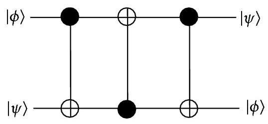
The SWAP gate is a fundamental two-qubit quantum logic gate that exchanges the states of two qubits.
The SWAP gate is represented by the following matrix:
\[ SWAP = \begin{bmatrix} 1 & 0 & 0 & 0 \\ 0 & 0 & 1 & 0 \\ 0 & 1 & 0 & 0 \\ 0 & 0 & 0 & 1 \end{bmatrix} \]
Operation on Basis States
- \(|00\rangle \to |00\rangle\) (No change)
- \(|01\rangle \to |10\rangle\) (Swaps qubits)
- \(|10\rangle \to |01\rangle\) (Swaps qubits)
- \(|11\rangle \to |11\rangle\) (No change)
Controlled Z Gate
The Controlled-Z (CZ) gate is a fundamental two-qubit quantum logic gate. It applies a Pauli-Z operation (phase flip) on the target qubit if the control qubit is in state \(|1\rangle\).
The CZ gate is represented by the following matrix:
\[ CZ = \begin{bmatrix} 1 & 0 & 0 & 0 \\ 0 & 1 & 0 & 0 \\ 0 & 0 & 1 & 0 \\ 0 & 0 & 0 & -1 \end{bmatrix} \]
Operation on Basis States
- \(|00\rangle \to |00\rangle\) (No change)
- \(|01\rangle \to |01\rangle\) (No change)
- \(|10\rangle \to |10\rangle\) (No change)
- \(|11\rangle \to -|11\rangle\) (Phase flip)

Toffoli Gate
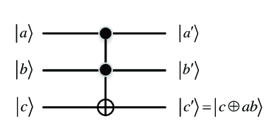
The Toffoli gate, also known as the Controlled-Controlled-NOT (CCNOT) gate, is a three-qubit quantum logic gate. It flips the target qubit if both control qubits are in state \(|1\rangle\).
The Toffoli gate is represented by the following matrix:
\[ Toffoli = \begin{bmatrix} 1 & 0 & 0 & 0 & 0 & 0 & 0 & 0 \\ 0 & 1 & 0 & 0 & 0 & 0 & 0 & 0 \\ 0 & 0 & 1 & 0 & 0 & 0 & 0 & 0 \\ 0 & 0 & 0 & 1 & 0 & 0 & 0 & 0 \\ 0 & 0 & 0 & 0 & 1 & 0 & 0 & 0 \\ 0 & 0 & 0 & 0 & 0 & 1 & 0 & 0 \\ 0 & 0 & 0 & 0 & 0 & 0 & 0 & 1 \\ 0 & 0 & 0 & 0 & 0 & 0 & 1 & 0 \end{bmatrix} \]
Operation on Basis States
- \(|000\rangle \to |000\rangle\) (No change)
- \(|001\rangle \to |001\rangle\) (No change)
- \(|010\rangle \to |010\rangle\) (No change)
- \(|011\rangle \to |011\rangle\) (No change)
- \(|100\rangle \to |100\rangle\) (No change)
- \(|101\rangle \to |101\rangle\) (No change)
- \(|110\rangle \to |111\rangle\) (Target flips)
- \(|111\rangle \to |110\rangle\) (Target flips)