Numerical Aperture and Transmission Losses of a Optical Fiber
Aim
Determination of the Numerical Aperture (NA) and transmission loss of the given optical fiber.
Apparatus
- Optical Fiber Cable (1m, 3m length)
- Fiber Optic Trainer Kit
- NA measurement jig
- Digital multimeter (DMM)
- Optical Fiber connector
Pre-Lab Questions
- What is total internal reflection? Give an example.
When light traveling from a denser medium to a rarer medium strikes the boundary at an angle greater than the critical angle, total internal reflection occurs, fully reflecting the light back into the denser medium.
Eg: Light traveling through an optical fiber. - How does the length of the fiber affect the measurement of transmission losses?
Longer fibers result in higher total transmission losses (in dB) due to increased absorption, scattering, and other attenuation mechanisms, allowing for more accurate measurement of the loss per unit length (dB/km) when dividing the total loss by the fiber length. - Write any two major advantages of optical fiber communication over other conventional communication system
Optical fibers offer high bandwidth, enabling faster and larger data transfers compared to copper cables. - Explain how the NA affects the choice of optical fiber for specific applications (e.g., telecommunications vs. medical imaging).
In telecommunications, low NA fibers (e.g., single-mode) are chosen to minimize dispersion and enable long-distance, high-speed data transmission. In medical imaging, high NA fibers (e.g., multimode) are preferred for efficient light collection and flexibility in navigating bends. - How might environmental factors (e.g., temperature, humidity) affect the performance of an optical fiber in real-world applications? in two lines
Temperature fluctuations can cause thermal expansion or contraction, altering the fiber's refractive indices and increasing signal loss or dispersion. High humidity may degrade fiber coatings or connectors, leading to increased attenuation or mechanical failure. - What are the basic components of optical fiber
An optical fiber consists of a core, which carries the light signal, and a cladding, which surrounds the core to enable total internal reflection. Additional components include a protective coating and, often, a jacket for mechanical and environmental protection.
Theory
The numerical aperture (NA) indicates an optical fiber's ability to collect light, defined as the sine of its acceptance angle. As a signal propagates through an optical fiber, a small portion is lost due to attenuation caused by various mechanisms.
Transmission Loss is given by
\[ Loss = 10. log_{10} \left( \frac{P_{in}}{P_{out}} \right) \]
For different lengths, calculate the loss per unit length (dB/km) \[ Loss per km = \frac{Loss (dB)}{Length (km)} \]Diagram
Working Formula
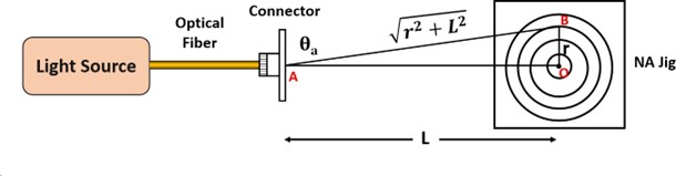
Mathematically, we can write numerical aperture as
\[ NA = \sin \theta_{\alpha} \]
In Right angle \(\Delta AOB\),
\[\sin \theta_{\alpha} = \frac{OB}{AB}\]
\[\sin \theta_{\alpha} = \frac{r}{\sqrt{r^2 + L^2}}\]
Where- r - radius of circle
- L - Length between the connector and measured circle.
By knowing the value of \(r\) and \(L\), \(NA\) can be calculated.
Procedure
Procedure for measuring numerical aperture
- Attach one end of the optical fiber to the light source and the other end to the NA measurement jig.
- Power on the optical fiber trainer kit.
- Observe the light output projected onto the jig, which displays concentric circles of known diameters. Position the jig at various distances from the fiber end and measure the radius (r) of the light spot corresponding to the circles.
- Record all measurements in a table and use them to calculate the Numerical Aperture.
Procedure for measuring transmission loss
- Connect one end of a 1-meter optical fiber cable (Cable 1) to the light source and the other end to a photodetector (PIN diode). Turn on the power supply.
- Plug the leads of a digital multimeter (DMM) into the output terminals of the optical power meter circuit.
- Set the DMM range to 0–2000 mV. Calculate the optical power in decibels (dB) by dividing the DMM reading by 10 (e.g., a reading of -165 mV corresponds to 165/10 = 16.5 dB).
- Adjust the power knob until the dB meter shows approximately 150. Record the output power (PF1) for the 1-meter cable.
- Disconnect Cable 1 and connect a 3-meter cable (Cable 2) to the light source and photodetector. Record the DMM reading (PF2) without changing the intensity knob.
- Use a connector to join the 3-meter cable to the 1-meter cable, forming a combined cable. Connect one end to the light source and the other to the photodetector, then record the power (PF3) for the combined cable.
- Repeat steps 4–6 for different power settings, such as 200 and 250 on the dB meter, to collect additional data.
Observation Table
| Sl. No | Radius of Circle r (mm) | Distance L (mm) | NA = \(\frac{r}{\sqrt{r^2 + L^2}}\) | Acceptance angle \( \theta_\alpha = \sin^{-1}(NA) \) |
|---|---|---|---|---|
| 1 | ||||
| 2 | ||||
| 3 | ||||
| 4 | ||||
| 5 |
| Sl. No | Output Power in Cable-1 (1m) PF1 (dB) | Output Power in Cable-2 (3m) PF2 (dB) | Output Power in Combined Cable (4m) PF3 (dB) | Loss in Cable 1 PF3 - PF2 (dB) | Loss in Cable 2 PF3 - PF1 (dB) |
|---|---|---|---|---|---|
| 1 | |||||
| 2 | |||||
| 3 |
Precautions
- Handle optical fibers with extra care
- Use it in a dust free environment.
Applications
- Broadcasting and Communication
- Mechanical Inspections
- In Medical surgeries
Post-Lab Questions
- Why is the refractive index of core medium slightly higher than that of cladding? answer in two lines
To ensure total internal reflection, which confines light within the core and enables efficient signal propagation in optical fibers. - Why is the data transmission fast in optical fibers rather than conventional metallic wires?
Optical fibers use light signals, which travel at the speed of light, much faster than electrical signals in wires. Additionally, optical fibers have higher bandwidth, allowing more data to be transmitted simultaneously without interference. - What are some other type of losses associated with optical fibers?
- Bending loss
- Absorption loss
- Scattering loss
Outcomes
After successful completion of this experiment, the student will be able to- Calculate Numerical Aperture of a optical fiber.
- Calculate the transmission losses in a optical fiber.
- Understand the usage of optical fiber in communication system